As an ARM authorised reseller, we tend to use the ARM Realview tools (RVDS) whenever appropriate. With ARMs recent acquisition of Keil there is now another option available, the Microcontrol Development Kit - MDK. MDK is aimed at the lower-end market - ARM7, Cortex-M3, and some ARM9. It is also targeted towards either OS-less, or RTX-based designs. RTX is ARMs simple realtime OS. It includes all of the features normally supplied with a small embedded OS: Threads, Scheduler, Mutexing, Memory Pools, Mailboxes, Delays, Events etc... When using the RTX kernel and the MDK tools together, a large number of advanced debugging options become available. The ability to trivially graph thread stack usage and thread execution time, which can make some aspects of profiling an application trivial. It also provides a full simulation system for a large number of CPUs (see the Keil Device List for more details). These simulated CPUs generally include the full peripheral suite as well, which makes prototype development easy, even in the absence of actual hardware. MDK also includes a full IDE, build system and large library of examples, making initial project creation a breeze. RVDS is targeted at a different market. It aims to support the latest ARM CPUs, with recent additions for the Cortex-A9. Its simulation model is geared more towards ARM cores rather than specific SOC chips, and as such it is not suitable for full system simulation. It can be used very well for algorithm simulation however, and provides all the optimisation feedback necessary for this purpose. Both of these platforms share the same compiler suite, RVCT. RVCT generally provides the best code generation and optimisation features of all the ARM compilers, certainly far better than the commonly used GCC compiler. It also supports a lot of the extensions provided by other tool chains, making it relatively easy to transition from one compiler to another. Generally, the decision between the two is quite apparent - if a more traditional embedded design is being done, such as an embedded control application, then a lower CPU, such as the Cortex-M3, or ARM7 will be chosen. In this case, MDK is more appropriate. If a more advanced design is to be used, involving a complex modern operating system such as Linux or WinCE and an ARM9 or greater CPU, then RVDS will provide faster code download & flexibility. 

- Error
RVDS vs MDKPosted in ARM Tools News on September 29, 2008 by Andre Renaud Cortex-M3 ExplainedPosted in Uncategorized on September 29, 2008 by Administrator Surely most engineers are familiar with the basics of the ARM7TDMI? To recap, it has a 32-bit register set with 16 registers, RISC load/store architecture, various processor modes with a role in exception processing, private registers in each mode (particular FIQ with a very useful r8-r14), a simple 32-bit instruction set with only 21 types and an additional 16-bit instruction set with zero-penalty decode logic. Since it was originally released in 1994, several of ARM's engineers wanted to improve on perfection. Perhaps the power consumption could be made even lower, perhaps the instruction set could be made even more dense, perhaps more microcontroller features should become part of the standard design? The shrinking area of silicon required for a microcontroller, and the resulting reduction in cost, presented another opportunity. It should be possible to make an ARM chip as small as an 8-bit micro, and to consume less power. Cortex-M3 is the result of these factors. It is not radically different from ARM7TDMI, and retains most of the architectural features. But it drops several, expands others, and adds a few more. Key features of Cortex-M3 are:
Bluewater, PCB Design & Fine-Pitch BGAsPosted in Hardware design on September 26, 2008 by Janus Patalinjug PCB design at Bluewater is most of the time an exciting challenge, especially when it comes with system modules. Just like with any other modern digital gadgets nowadays, they have to be small in size and thus, space (or real estate as another term used by PCB designers) on a PCB is always a premium. Along with this direction, the chain must adapt to it, small fine-pitch and high density components are mostly used, PCB vendors have to update their capability, as well as PCB assembly houses. And of course, cost will always be involved when going to miniature, complicated technology. Otherwise, these modern tiny gadgets will never exist. Speaking of fine-pitch high density components, things like 0.5 to 0.65mm pitch BGA packages should usually surface as a common option along with fine-pitch packages such as QFN, DFN, etc. The thing with fine-pitch BGAs, especially full-matrix ones, is that they are usually more difficult to fan-out (so that you can route to the rest of the circuitry on the PCB) compared to conventional0.8 to 1mm pitch BGAs. High-tech PCB technologies such as Two year ago, we developed a module (37mm x 26mm) with Intel's PXA272 microprocessor (0.65mm-pitch, 336 pins, full matrix BGA) on it for our customer (in military defence). With cost in mind and by coordinating with our PCB vendor, we were able to avoid the costly high-tech HDI or blind/buried microvias, or via-in-pad by using 5-mil via through-hole drill/15-mil via pad and 3-mil spacing between vias to any other entities but with limited aspect ratio. Although this approach may still not fall under (still slightly expensive) the conventional PCB technologies and is dependent of our PCB vendor, at least it's not a full blown HDI or any other costly cutting edge PCB technology and it's good to know that there are less costly options like this, especially when just producing prototype quantities. In our Snapper 270 SOM, we also have buffers having 0.65mm pitch but not full-matrix ones and we were able to use full conventional PCB technology by carefully assigning signals on the buffer side to eliminate vias in fanning out the BGA and optimised routing. Most recently, we are currently developing our Snapper-DV board, which is using Texas Instrument's Da Vinci processor TMS320DM355, a full-matrix, 377 pin, 0.65mm pitch BGA and again, the same above mentioned strategy were used to check cost and this time around, with an improved aspect ratio, thanks to our PCB vendor. PCB Material of RoHS Compliant ProductsPosted in Hardware design on September 26, 2008 While working on a project for the UK market, the issue of Printed Circuit Board material came up. As this product was required to be RoHS compliant (Restrictions of Hazardous Substances Directive), it must be able to withstand the higher re-flow temperatures associated with lead free soldering, which can peak at 260C. A common misconception with this is that using just a higher TG (Glass Transition Temperature) will be acceptable. However, you will also need to ensure your base material is also of a higher TD (Decomposition Temperature). The TG value is where the resin changes from rigid to soft material and TD is the value where the material weight changes by 5%. Exceeding the TD value will cause permanent damage to the circuit board, which can result in loss of adhesion and delamination. See the link below for a more detailed and in depth read. www.isola-group.com/images/media/ReengineeredFR4Materials.pdf So when selecting PCB material for the lead free solder process, a good guide is to use material with TD above 340C and TG above 170C. 3G ModemPosted in Uncategorized on September 25, 2008 by Administrator
3G data modem support is a core feature for the Real Time Passenger Information (RTPI) system designed by Bluewater Systems. The RTPI system is designed to collect and display information about the arrival times of buses at a particular point on the route. This information is provided by a unit on the buses which uses a GPS receiver and GPRS or other wireless communications to pass on positional information to a central server. The choice of the 3G modem was dictated by another requirement: to use a cheaper GSM data modem as an assembly option. Bluewater decided to use the 3G embedded module MC8775 from Sierra Wireless, a low talk and low standby current modem which comes in PCI Express Mini Card form factor.A Sierra Wireless MC8775 PCI Express Mini Card supports third generation (3G) digital cellular standards and it is globally certified. An MC8775 supports tri-band UMTS (HSDPA): 850/1900/2100 MHz, with forward link up to 3.6Mbps, and quad-band EDGE/GPRS/GSM: 850/900/1800/1900 MHz, with forward link up to 216 Kbps. Although the data modem has a PCI Express Mini Card form factor, it does not support a PCI Express electrical interface. The host and USIM interfaces, as well as power supply for the 3G/GSM modules, are provided via a PCI Express Mini Card connector. The communication between the 3G data modem and the host (Snapper CL15 module) is provided via a USB 2.0 interface. The PCI Express Mini Card form factor allows a simple downgrade path if it is cheaper, however, the same form factor GSM data modem designed by Bluewater Systems is desired. Another benefit of having the same form factor for 3G and GSM data modems is a smaller main board and a simple upgrade/downgrade path. |
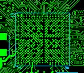 In the near future, HDI and the like may be the only way to go but hopefully, the cost tagged along with using these cutting-edge technologies will trick down (fingers crossed).