Posted in Uncategorized on December 15, 2008 by Andre Renaud
For several of our projects we have had to use a Logic Analyser to determine the proper working of an existing system. The results of a captured session on the Logic Analyser is a large binary file representing the state of all 136 of its inputs, over a period of time, at around 2ns granularity. This gives an enormous amount of data which must be then viewed by the operator to determine where a problem lies. Some aspects of this can be eased through the user interface on the Logic Analyser - colouring relevant lines, or giving textual labels to certain values. But mostly it is a manual process. We have developed a protocol definition system which allows us to describe the protocol, and then automatically process the traces from the Logic Analyser, decoding the results into a human readable form. This give a double benefit - we can analyse an existing system to determine how it is working, producing our parser as we go, and once this is completed we can then run it against our own implementation to verify that it conforms to the original system. As the Logic Analyser is a completely generic digital interface, it can process almost any signaling system. Using this technique we have written protocol definitions for the following buses:
- 8250-compliant UART bus
- Kennedy tape drive bus
- Pertec tape drive bus
- SCSI bus
- NAND control & data bus
- PCI bus
- SPI bus
- CFI-compliant NOR flash bus
- DM9000 Ethernet controller bus
- Image Sensor interface bus

Posted in Uncategorized on December 15, 2008 by Administrator
We are currently working on two camera-based products: our own Big-Eye security camera system and a small hand-held digital camera. Both of these cameras have the requirement of a user being able to connect to them from a desktop computer to manage and download the images. However, the primary connection method for Big-Eye is Ethernet, while the other camera uses USB. There is a standardised protocol called PTP (Picture Transfer Protocol) which has specifications for both IP and USB. PTP is a widely recognised standard. It is used by most consumer digital cameras and is supported 'out of the box' by most major operating systems.
PTP allows users to download images (and other files) from a camera and delete unwanted images. It also supports camera properties which can be used to view and control the camera's date and time, exposure time, battery level, etc. In developing software support for PTP on our camera products we have written a generic, transport independent PTP layer, which implements each of the PTP commands and properties, and also contains code for managing the images on a camera. This generic layer calls transport specific (IP or USB) functions for sending and receiving data packets. The major benefit of this approach is that any new features, or bug fixes, we make to the generic PTP layer are automatically inherited by both the IP and USB cameras.
Combining this PTP code with the image capture software develloped for Big-Eye (which includes featuers such as threaded image capture, Bayer conversion and JPEG encoding) we now have a full Linux-based software solution for consumer grade cameras.
Posted in Uncategorized on December 11, 2008
The RoHS EU directive that came into affect in July 2006 banned 6 substances from being used in electrical and eletronic equipment. However, since then, others have come on board with their own version of the directive. Look at China for instance. Although China bans the same materials, they do it in a different way and in some areas they are more strict on what is required for compliance. See http://www.rohscompliancedefinition.com/china-rohs.html California also has laws that prohibit 4 of these substances since January 2007. These being:
- Cadmium
- Hexavalent Chromium
- Lead
- Mercury
These directives to nee to be regularly checked to insure that any changes to these are adhered to. This is particularly important if your product currently falls under an exemption as the requirements may change. It is also important for each company selling into these markets to make a statement on what is considered due diligence. That way, its employees know what is expected of them and what the ramifications are for not following the required process. A good description can be found here:
http://www.rohscompliancedefinition.com/due-diligence-rohs.html
Posted in Uncategorized on December 11, 2008 by Administrator
The new release of software (3.3) for the RealView ICE supports Texas Instruments' range of OMAP3 processors. An interesting feature of the OMAP3 family of processors is that the ARM Cortex-A8 core is not automatically added to the scan chain and cannot be auto-detected. Instead the OMAP3 uses a TAP router (JTAG Route Controller) that must be programmed with what is available on the chain. Luckily ARM has provided "templates" for the OMAP3 family that allow the user to select which processor they have connected to. The template provides the RealView ICE all it needs to know for easily connecting to the ARM core. An example of the OMAP3530 scan chain is shown below. 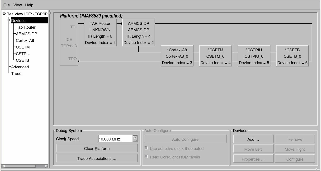 Also be aware that TI uses a non standard 14 pin JTAG connector. If you need to connect any of the standard ARM JTAG tools to a TI (such as the OMAP3 family) processor, you will need a TI JTAG adapter such as the ARM provided HBI-0027B (Schematic). Make sure you mention you need to connect to a TI device when you purchase your next RealView ICE!
Posted in Uncategorized on December 04, 2008 by Administrator
Bluetooth and Wifi (802.11b/g in particular) have two things in common: they're both increasingly ubiquitous in embedded devices, and they both use the 2.4 GHz frequency band. Although resident in the same part of the frequency spectrum, Bluetooth and Wifi use markedly different approaches to transmission management and collision avoidance. As a result, devices (or event localised areas) with both Bluetooth and Wifi active are prone to conflict and service degradation - in extreme cases, leading to wireless networking being completely unusable. The basic issue is that Wifi breaks down the frequency range into 14 channels, and transmits on a fixed channel. Bluetooth, on the other hand, hops between 79 channels at a rate of up to 1600 hops per second. When a Bluetooth transmission happens to coincide (in time and frequency) with a Wifi packet transmission, both transmissions may be lost. Due to the longer packet sizes, this has a far greater impact on Wifi transmissions, at worst leading to a cycle of packet loss, Wifi transmission rate dropping (thus increasing the risk of collision), and further packet loss - terminating in complete loss of Wifi connectivity. To address this problem there are a few basic approaches: 1. Limit inter-device interference via distance or shielding. By providing 25dB or greater isolation between antennas, the issue may be avoided entirely, but this is often not practical for small devices. 2. Activity signaling and time sharing. Many Wifi and Bluetooth modules provide signals indicating that transmission is currently in progress, or to defer non-critical transmissions. This avoids interference, since only one device is transmitting at any given point in time, but can adversely impact performance. 3. Channel signaling. Interference only occurs when both Bluetooth and Wifi attempt to transmit on the same frequency range, so notifying the Bluetooth module of what frequency slots to avoid during its hopping sequence can avoid interference with no loss of Wifi bandwidth, and minimal impact on Bluetooth. 4. Adaptive Frequency Hopping. The Bluetooth v1.2 standard outlines a mechanism for Bluetooth devices to automatically mark and avoid frequency slots that exhibit interference from other devices, this preventing interference for both Bluetooth and Wifi. Unlike the other solutions listed, this does not require special board-level support, but is only available where all devices in a network support it. These schemes typically rely on module extensions and require board-level support, and vary in terms of the types of interference they can address effectively. In particular, these solutions may be limited where there is broad-base interference or where communication between interference sources is impossible. A simple general solution is therefore not achievable, so care must be taken when doing board design and module selection to take these issues into consideration, and to address the specific coexistence needs of the product.