In drawing up the schematics for a new design, it is very easy to add new components willy nilly as and when required. Then - once happy with the design - move on and produce a masterpiece of a PCB layout. After the PCB layout send the files out for quote and move on to purchasing components. It's at this point that you may find yourself confronted with a large BOM (Bill of Materials) to buy before you can build your board. The time to find and buy these components is not the end of it either. A large BOM has the following drawbacks:
- The more discrete part types in a design, the lower the volume of each will be, and the cost benifit of buying in bulk can not be realised
- The inavalibility of any part can stall a build. The more parts in a build, the more likely this is to happen
- More parts means longer machine setup times and more feeder requirements - possibly even a double pass through the machine. These all add to build cost
- More components to track and keep inventory of which costs time
On most boards there are a variety of very simple things that can be done for very low cost to mitigate these problems - the initial cost will more than pay for itself in reduced future costs and reduced risk.
The BOM rationalisation step should be performed after the schematic phase - NOT after the PCB phase. Often BOM simplification requires trivial changes in the schematics, but once the PCB layout is done changes may result in a lot of work needing to be redone.
There are many things that can be done to reduce the BOM count. Resistors and Capacitors are the simplest place to start: often there is a wide range of these in any design and these are by far the easiest target. There will often be many components of which there is only one or two used. Several things can be done in this case:
- Check if the odd-ball specific value is actually required, or can it be replaced by a more common component on the design. Pull-up resistors are a common culprit here
- If the value is required, see if it can be produced by a parallel or series combination of common components. It is quite suprising how often this technique can be used.
- Voltage dividers. These can be a special case of the above technique. In one recent design, it was discovered that a 100k, 120k and 330k could produce over 60 different divider ratios with one or two high side resistors, and one or two low side ones. The spread was quite even too.
Power supplies can often be simplified too:
- Using an adjustable version of a power supply, and tailoring it to several different voltage rails will use fewer different ICs than using the pre-programmed ones. When it comes to production, a shortage of any IC could put a halt to productio, so the fewer different IC types, the better
- Adjustable supplies normally have a voltage divider to set the output - take advantage of the voltage divider options as discussed above. Remember that a 3.3v supply doesn't need to be 3.300000000v: 3.27453v is more than acceptable for the vast majority of systems!
- Inductors can often be reused on switch mode supplies even though it is a different voltage rail. It may sacrifice a minor % of efficiency, or on the surface cost a few cents more - though doubling the volume will more than likely cancel this out.
- Don't be afraid to understand and modify the 'webbench' recommendation. TI, National, etc all have really easy to use web based tools for designing power supplies, but don't take the design they provide as the end of it. There is scope for adjustment and fine tuning to suit your particular board
- Some switch mode ICs can be configured as a DC/DC converter, or as a current source for driving an LED backlight. Look into these options at design time and use the same switch mode IC for both
Similar components can often crop up in designs. If there are multiple different types of MOSFETS, BJTS, or diodes these can be reviewed to ensure that there is a good reason for them to all be different. This is most often a problem when portions of several designs are combined to make a new one.
Use configurable logic gates - TI for one make some small ICs (SN74AUP1G57 for example) that can be wired up as an AND gate, an OR gate, or some other odd-ball gate. These can have their advantages if there are several different gate types in the design that can each be replaced by a different version of the single configurable gate.
Consider for some applications using transistors and resistors to replace a one-off logic IC.
There are many more things that can be done. The majority take very little effort at the schematic phase. It is easy to be of the mindset that that 12.7k resistor only costs a few cents, so why bother removing it, however the issue is not the cost of the component - it is the cost of supporting the component! The 5min to design it out pales when compared to the what it would cost to support it through the lifetime of the product through purchasing, stocking, machine setup, and risk of it being temporarily unavailable.
Here at Bluewater we strive to keep BOM counts down and this approach has produced dividends both in simpler prototype and production builds. The benefit is easier stock tracking and reduced time spent on component managment.

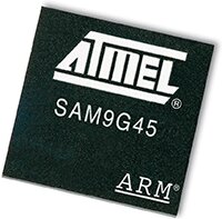 ave managed to boost the clock speed, increase the peripheral set, reduce the power, and reduce the cost all in one go. These new chips, the