Power over Ethernet
Introduction
Power Over Ethernet (PoE) is a relatively new power distribution technology which allows DC power and data to be delivered simultaneously over the existing LAN wires. Similar to traditional telephone systems, where the phones are powered through the same wires used for voice transmission, the PoE capable devices can be powered through the same wires used to send data rather than by a power cord.
Power Over Ethernet technology is used to power many types of Ethernet devices, such as IP telephones, wireless access points and network cameras. Virtually any network device that can run from 13W or less can operate off the RJ-45 connector alone.
The major benefits of PoE technology are:
- lower cost - no need to run separate data and power wires to every network device, and separate power outlets are required,
- reliability - if PoE is implemented with battery backup (or uninterruptible power supply as is often the case), the network devices (IP phones for example) will operate even if the main power is down,
- flexibility - more freedom to choose the optimal access point location from performance/coverage point of view rather than limited by the location of existing AC outlets,
- simplicity - no need to provide different device versions for various countries (different power supplies, power cords etc).
PoE System
The Power Ever Ethernet implementation is defined by IEEE 802.3af standard. An IEEE 802.3af (PoE) compliant network has two major components:
- Power Sourcing Equipment (PSE) - a device that supplies power and
- Powered Device (PD) - a device that draws the power from the wire.
PSE (Power Sourcing Equipment)
A PSE is typically an Ethernet switch, router, hub or other network switching equipment. There are two types of PSEs: endspans (Ethernet switches that include the PoE transmission circuitry - PoE switches) and midspans (power injectors connected between regular non-PoE Ethernet switch and the powered device).
An IEEE 802.3af compliant PSE is required to provide:
- a nominal 48V DC between either the signal pairs or spare pairs (but not both),
- 48V supply isolated from the PSE chassis ground,
- minimum 15.4W () power supply,
- a valid PD signature detection before applying power to the wire,
- turn on within 1 sec after PD is plugged in (for single port only),
- supply at least 400mA for 50 ms without current limiting.
To minimise the possibility of damage to equipment in the event of a malfunction, the more sophisticated PoE systems employ fault protection. This feature shuts off the power supply if excessive current or a short circuit is detected.
When a network device connects to PoE network, the PSE has to determine if the connected device is a PD or not. This step is necessary in order to prevent non-PoE network devices from receiving power, which could cause damage. The PSE applies two small current-limited voltage signals across the cable as it checks for the presence of a characteristic resistance (25 kOhm). If correct resistance is detected, PSE will provide the power. A PSE may optionally check classification signature that indicates the maximum power the PD will draw.
After the PSE has discovered a PD, it supplies 48 V and a maximum current of 350 mA. Taking into consideration the voltage drops along the network cable, a minimum of about 13 W is available to each PD.
Once the PSE begins to provide power it must continuously monitor the PD current draw. If the PD current consumption drops below a minimum value, the PSE must wait between 300ms and 400ms before disconnecting the power supply and starts the discovery process again.
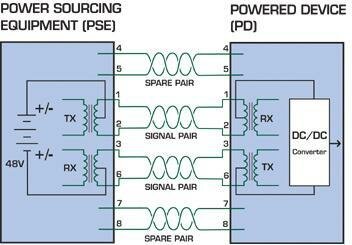
Figure 1 - Power Supply over the Data Pins

Figure 2 - Power Supply over the Spare Pins
PD (Powered Device)
A typical PD can be Voice-Over-IP phone, a wireless access point or almost any small Ethernet device. A PD receives the power over the standard CAT-5 network cable via an RJ-45 connector and it must meet several criteria to comply with IEEE 802.3af:
- must be able to accept the power over either the signal pairs or the spare pairs,
- must be able to implement auto-polarity (since the signal pairs can be either polarity),
- must present a characteristic 25 kOhm signature impedance at the beginning of discovery process,
- an optional classification signature may be presented to indicate the maximum power the PD will draw,
- must not draw significant load current until the input voltage rises above 30V,
- must be fully operational by the time the input voltage reaches 42V,
- must never draw more than 350mA or 12.95W continuously, whichever is less.
A PD may not use the data link at all, but only the power - as an example, a cell phone battery charger can draw its power from an Ethernet connection.
Summary
Power Over Ethernet is a technology that integrates data, voice and power on standard Ethernet infrastructure providing new options for power distribution. It provides reliable, uninterrupted 15W max (13W load), 48V nominal supply to the devices connected to the Ethernet using existing infrastructure. This allows IP telephones, wireless LAN access points, surveillance cameras and other embedded appliances to receive power as well as data over existing CAT5 cabling. Implemented according to an international standard, Power over Ethernet is established as an economical, safe power distribution method already deployed throughout the world.
In order to satisfy the increasing demand for more power for evolving application applications such as motorised network cameras, IP telephony video phones, laptops etc., IEEE started reviewing new PoE specifications, the higher power version of PoE called PoE Plus (IEEE 802.3at). The major improvement in new standard is the increased power rating to the 30 to 60 watt range. It is expected to be ratified in 2008.
More information about Power over Ethernet can be found at poweroverethernet and Wikipedia.
Bluewater Systems Experience
Bluewater has used PoE technology (both PSE and PD) in several projects, including:
- On Board Unit for Real Time Passenger Information (RTPI) system, designed to collect and display information about the arrival times of buses at a particular point on the route (project Trumpeter). The system includes four-port PoE PSE Ethernet switch. Every port is able to supply 15.4W (), with total power required 61.6W. An IEEE802.3af fully compliant PoE PSE is based on two major components: PSE power manager and 24V/48V DC-DC converter. The PSE power manager controls four ports in a PoE system. It operates in Auto Mode of operation, performing discovery, classification and delivery of power autonomously to a compliant PD.
- RIG200 Development Platform as an IEEE802.3af fully compliant PoE PD. Rig 200 can be powered over the twisted pair RJ45 Ethernet connector. This can power the board as well as charge the Li Ion batteries. The maximum power available to Rig 200 is 12.95W, as per IEEE 802.3af specification. However, power supply efficiencies will reduce this to closer to 10W.