
GPIO
Introduction
General purpose input/output (GPIO) pins are one of the most common form of input and output control in embedded systems. ARM microprocessors typically provide a large number of GPIOs for general use. GPIOs usually have a number of associated registers on the microprocessor for controlling the direction (input or output), value and type. In output mode, a GPIO can be driven either high or low to control some external peripheral. In input mode, the value of a GPIO can be read to determine the state of the externally connected pin.
GPIOs can be used for a number of functions:
- Turning LEDs on and off.
- Reading the value of a DIP switch.
- Reset and control lines for a wide range of peripherals.
- Simple buses. For example the Snapper CL15 uses two GPIOs for the EEDAT and EECLK lines of the I2C bus.
Some GPIOs can have multiple functions. One of the most common alternative functions of GPIOs is to provide interrupt sources. Often a register will allow configuration of the interrupt as active high or low, edge or level triggered. The GPIO is configured as an input and can still be read normally. However, it will trigger an interrupt, which can then be handled in software, when the appropriate signal appears on the GPIO. Some microprocessors also multiplex GPIOs, so that an alternative function can be used if the GPIO is not required. For example the Snapper CL15 has several GPIO pins multiplexed with the IDE controller.
Bluewater Experience
Tape Controller simulator


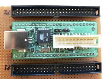
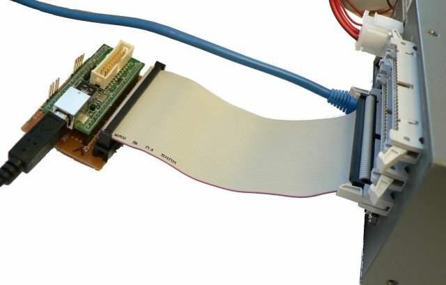
When developing the DDS XM-100 [1] we often had to debug the tape emulation system when we did not have access to the exchange controller. To work around this we developed two simulators, which perform the same operations as the exchange controller. We did this using our in-house UDIP module [2] and a simple bread-board connector to convert it to the correct pin-out.
As the UDIP module is dedicated CPU, it is able to perform quite accurate timing on its pins, and we were able to significantly ease our debugging effort by providing an easily accessible test kit for our final production units.
OLED development
GPIOs are also useful when doing proof-of-concept prototyping work. When doing exploratory development, use of a custom board is often not possible, preventing the use of conventional buses. In these cases, it is often useful to directly wire a component being evaluated to GPIO lines - a mechanism currently being used in-house to evaluate the feasibility of an OLED display on Snapper units.
Extendible FPGA-based GPIO
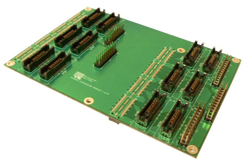
When using the Snapper255, it is possible to use an FPGA core that include a GPIO controller which we have developed. This controller allows for any FPGA pin to be accessed directly from the CPU, for either input or output. These lines can be used as an interrupt source, for either level or edge sensitive interrupts. Due to the large number of FPGA pins, this puts the number of external interruptible sources available to the 255 module at around 150.


