
Bringup
Overview
When a new board is produced, its design needs to be verified, and the appropriate software ported or developed to turn it into a working development platform. This process is known as 'bring-up', and is generally one of the longer processes in the initial development plan
Test access

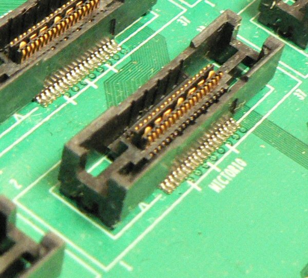
One important point that is often over looked when designing a new board is test access. There is a distinct trade off between the additional effort required to bring a variety of signals up to an appropriate header, versus the cost that can be incurred during bring-up when trying to track down a fault where insufficient test access is available. When designing a completely new board, especially if a new CPU is involved, we generally err on the side of test access, providing as much test access as we can. This generally results in a board which is physically much larger than the final product will be, as the test connectors can be quite large.
Bring-up Stages
At various stages during bring-up, it can unfortunately occur that a mistake has been made in the board design, requiring some aspect of modification. These 'mods' can range from simple single-wire alterations to redirect a signal to a more appropriate location, to full chip replacements due to incorrect footprints.
Power supply verification

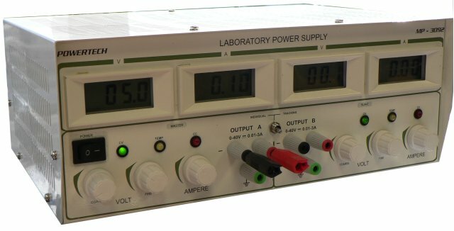
When a board first arrives back from the manufacturer, we initially start by looking at the power supply. Using current-limiting bench power supplies is absolutely vital at this stage, as if there is any board fault it is possible to over-current the board and destroy components if not careful.
Core functionality
The first aspect of the software bring-up is the CPU core itself, as well as the SDRAM, and generally one of the UARTs. The SDRAM is vital to all further bringup, and the UART is generally required by further software such as the bootloader or operating system. When performing this core bring-up, generally we use the ARM RealView suite of tools. These provide easy access to the core registers of the micro, as well as having very fast access to the device. See RVI Virtual Ethernet for more details.
Boot loader development
Having got a running core, generally getting a boot loader onto the device to ease further development is the next concern, especially if the device supports Ethernet, as this will allow for fast download of the operating system later on. The generally the initial boot loader bring-up will focus only on the UART and Ethernet, and once these peripherals are working satisfactorily the remaining boot loader customisation will be left until later.
Operating system port
The specifics of this stage depend on which operating system has been chosen for the final device. However in general this stage involves looking at each peripheral of the system in turn, getting working drivers running, and ensuring that they provide a suitable interface to the final application software.
Test tools
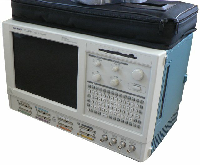
An important aspect of bring-up is testing - how to confirm that the board behaviour is good. For some systems this can be quite simple, however in cases where the interaction is with an external system, it can be quite involved. This can occur when the device being developed needs to communicate with a pre-existing system. Often this system is not readily available for testing against, or it may require some additional interfacing system which has yet to be developed. In these cases test equipment such as logic analysers, or oscilloscopes can be used to verify the correct operation of the device.
Bluewater Systems Experience

When developing the DDS XM-100 product, the physical characteristics of the tape controller interface was often not described very well in the manuals we were provided. The majority of these details were gained by reverse engineering the protocol using our Logic Analyser. We were able to use the analyser to capture traces of specific tape operations, and then using some internally developed custom analysis software extract the exact protocol timing information. We could also use this to compare the performance of our unit with the original tape devices.
Bluewater Systems Test Equipment


At Bluewater we have have a large array of test equipment, including:
- Tektronix TLA5204 128 channel Logic Analyser
- Tektronix TLA714 96 channel Logic Analyser
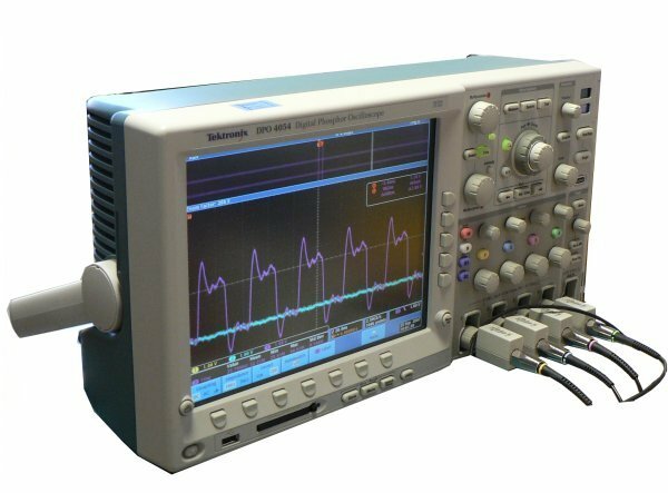
- Tektronix 4054 4 channel high speed Oscilloscope
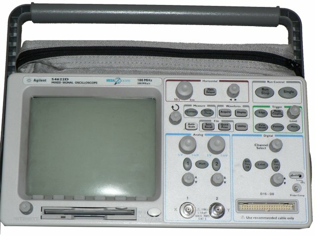
- Agilent 54622D 2-channel Oscilloscope, with 16 additional digital channels
We also have a variety of board re-work tools including a large array of temperature controlled soldering irons, and an SMD rework station.